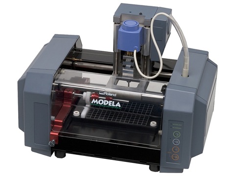
THis is MODELA MDX -20
This week documents chronologically the exploration of making PCB's
MODELA MDX-20 is a desktop CNC mill , which also has the option of scannning . MODS program is to generate the tool settings . Various tool settings such as tool diameter speed and RPM can be easily set . MODELA requires a ".rml " file . It is communicated over the serial port .
THis is MODELA MDX -20
A sacrificial layer of polycarbonate was laid down over , a layer of foam tape . Initially we realised the level of the sacrificial layer was uneven. This was found out by using a spirit level. The leveling screws of the beds were adjusted accordingly.
Milling of the PCB's created various challenges . such as due to the unavailablitly of tape , PCB counld not be properly mounted , during milling the outline of the board the PCB moved thus destroying the board . This was rectified using a fixture of cellotapes which was stuck around the board . Before the setup was done the gravity was adjusted . and milling was started . I found out that the gravity set was incorrect as it was not milling the board properly . This was because of 2 reasons 1. The stock had a curvature in the middle and the machine had a uneven incline .
A milling bit which was mounted broke almost instantly when it touched the board. Were testing out new milling bits.Old milling bits generate vibrations and generate lots of "burr" while milling the tracks.
THis is the view mode of the Modela
THis is the pcb fabrication process
This is the process by which the boards were milled. As you can see from the GIF . The cooper stock board is put on the the machininig bed . The end mill is set in position using the FAB-Modules setup . After this the endmill is lowered to the board . The grub screw is loosened and the mill is dropped to the level of the copper stock board . Slightly taping the board should do the job but i found this would make the endmill pass over the pcb and polish the upper layer of the board instead of milling it . I found slightly pressing the board and then setting the gravity helps .in making sure the board is milled properly .
The entire process involved setting up the sacrifical layer of polycarbonate layer.Soldermask has not been listed on the fab inventory list . I opened the Altium application . I could not find the option for exporting the png output in the file. So after cracking my brain over I generated gerber files which were exported in the png format . I resized the file after measuring the milled board. The png file of the board was measured in Illustrator and Photoshop .
This GIF illustrates the process from which I extracted the pads files. This was done by using existing design files which I was able to use to generate the pads only file which is basically the solderlayer which will be used in automated assembly to denote the pads .
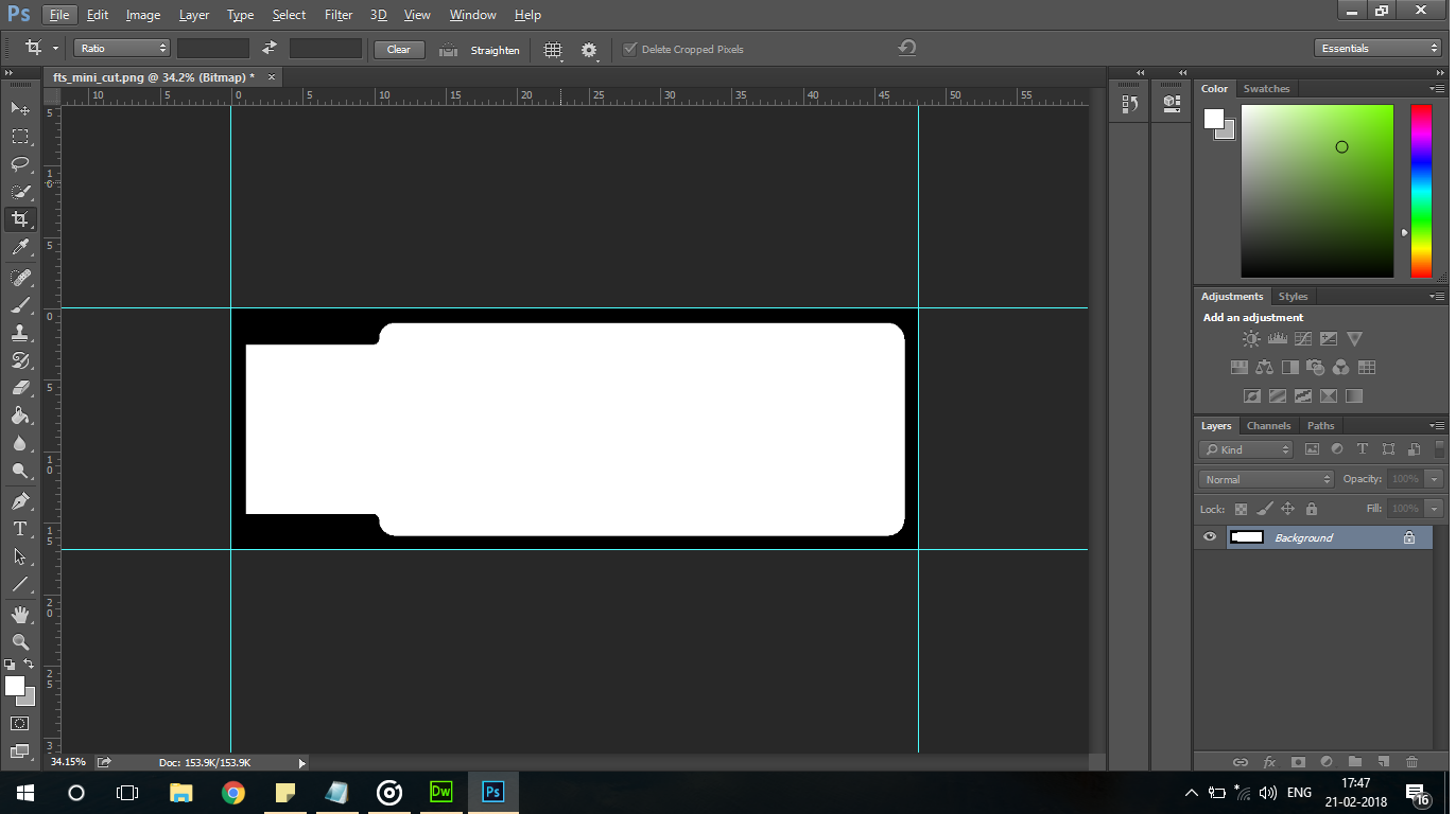
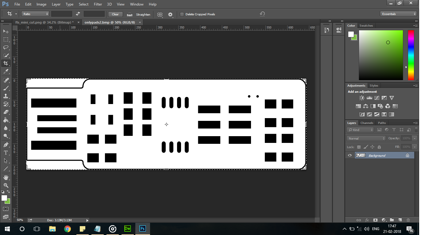
Measuring the units of this file in Photoshop . I measured the png file in Photoshop 2014 to make sure the dimensions of the generated file equal to the physical size of the board .
Measuring the bmp of the file which was generated in Altium
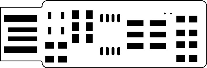
The file which was used on the vinyl cutter . Only thing which needs to be done is "resizing the image" to height at 48mm .
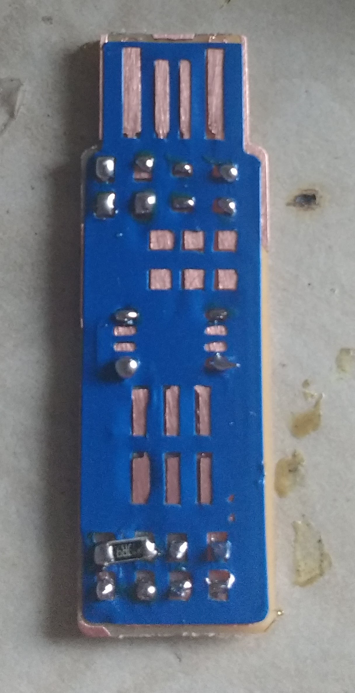
Vinyl stuck on the milled board made an excellent mask . Neil suggested a white epoxy covering for the PCB . This will de done in the following assignments .
Soldermask has not been listed on the fab inventory list . I opened the Altium application . I could not find the option for exporting the png output in the file. So after cracking my brain over I generated gerber files which were exported in the png format . I resized the file after measuring the milled board. The png file of the board was measured in Illustrator and Photoshop .
Vinyl worked out well for solder gun temperature . It was getting deformed at high temperature . I am planning to cut out high temperature materials . Following attached are the images for the vinyl process.
The vinyl was purposfully destroyed .
Vinyl covered PCB is extremely helpful for a novice person who can get started in the field of soldering .
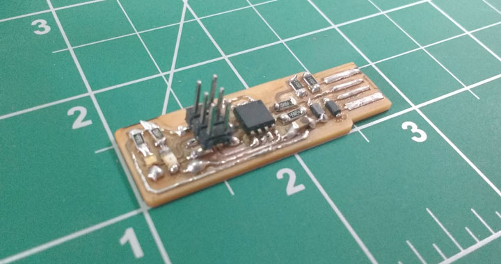
Final Board which is soldered . I will be working on my soldering skills .
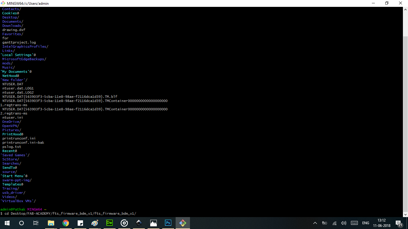
Installing the GIT BASH and navigating to the Firmware Folder. This is the same insterface for Linux Commands.
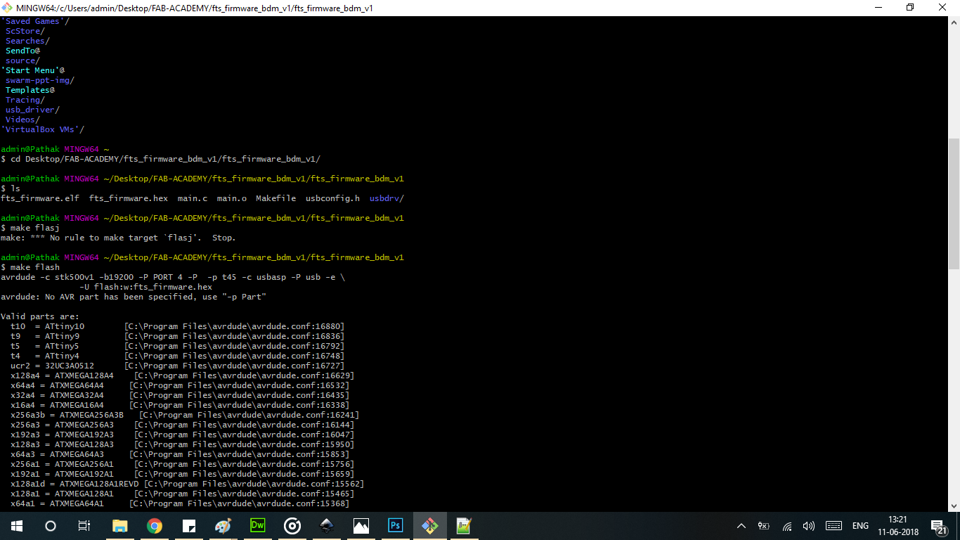
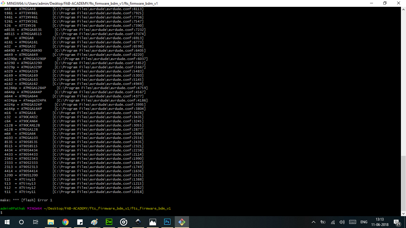
There was an error in the make file as it was not edited or properly declared . This lead to generation of these errors .
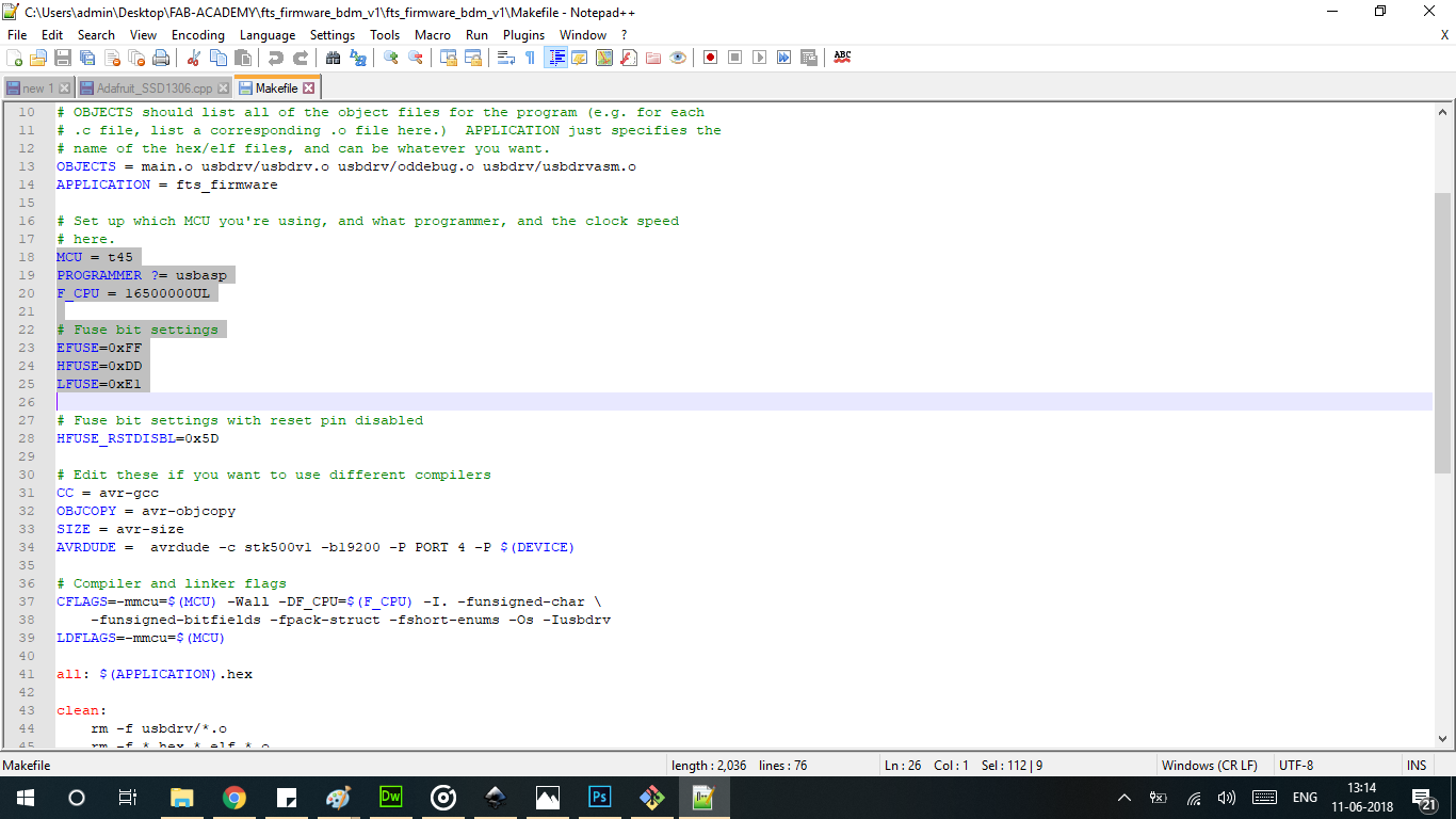
Editing the make file . The FAB-ISP was programmed on Kamlesh's Laptop is the attached screenshot are of his Laptop . Screenshots coming Soon
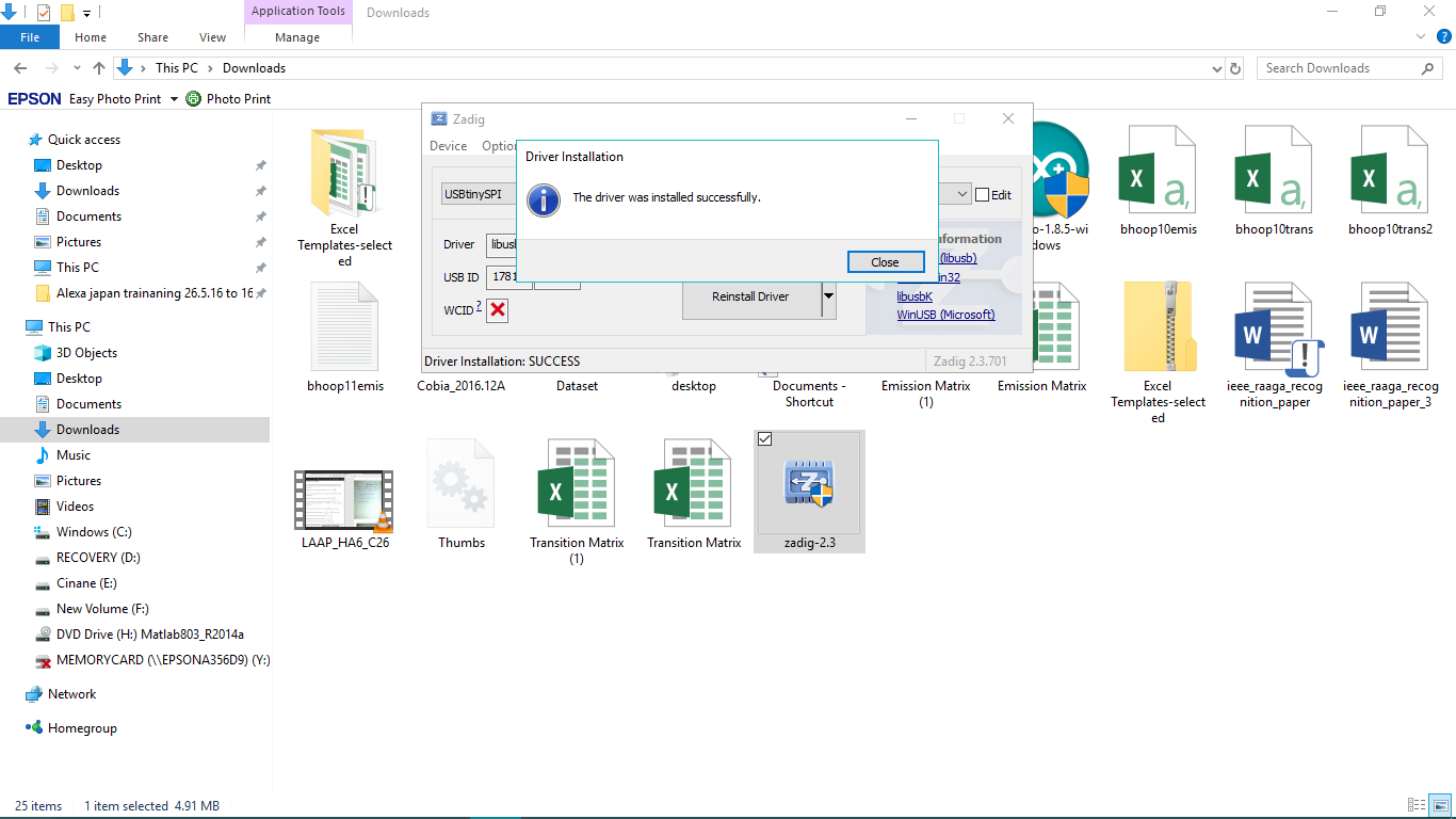
Installing the driver " ZADIG " on the laptop .
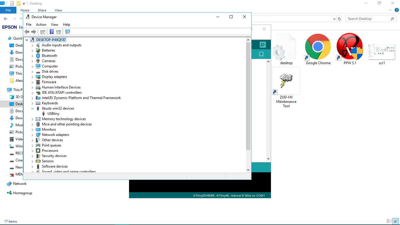
Device detected on the Laptop ( Check in the Device Manager )
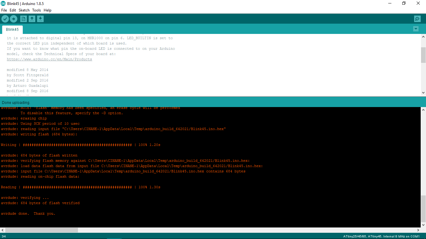
FAB-ISP operational and functional . As seen from the screenshots . The commnents indicate the successfull uploading of code .
This video shows the sucessfull burning of code on Output Devices Board. In this video I have uploaded the LED Blink Code.
PROBLEMS FACED
One of the problems faced was the gravity of the bit is was wrong . On that particular setting ended up polishing the board instead of milling it . Pressing on the endmill leads to them breaking . This is one of the most critical inventories of the entire FABACADEMY .
There was a lot of driver issues with Windows 10 . FAB ISP on my computer is not detected but it is detected on other Laptops with windows 10 . I could also not program it from my PC . I had to take help of Kamlesh who has a laptop which is running Ubuntu.
Learning electronics production. Using Modela for milling the board using MODELA MDX-20. Practising soldering and using a hotair rework station. This was the assignment where i was i learnt about V-USB which is basically 8 pin chip emulating as a USB programmer .